Old version Video
Old Version VacTubAmp. Vacuum tube amplifier with EL34
VacuTub2 In progress, project name VacuTub2306. 2.Push-Pull ultra linear vacuum tube amplifier
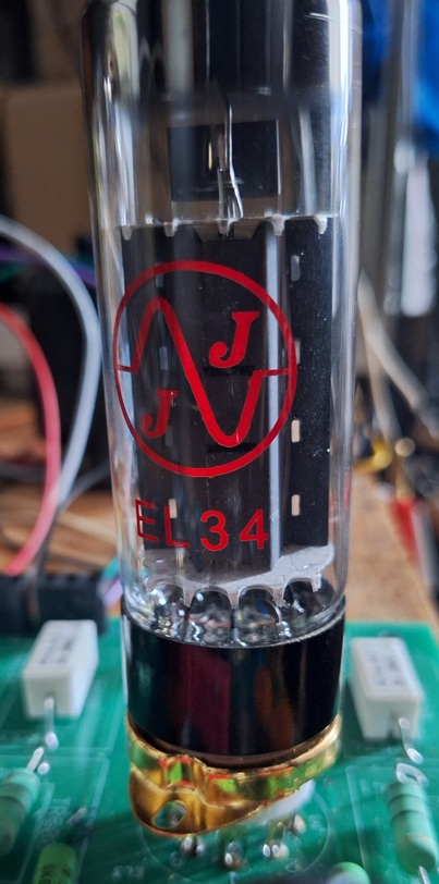
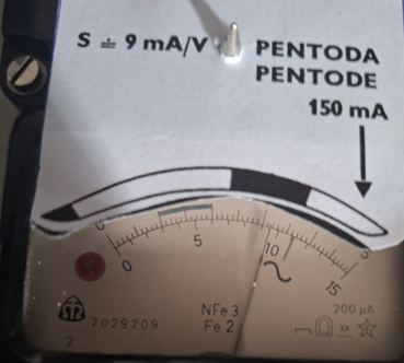
Two (four) power vacuum tubes (JJ Electronic EL34) are used to amplify phase-inverted copies of the same signal..
The output power depends on the output transformer, only the recommended current and voltage values for the EL34 anode are allowed !!!
Send us your question.
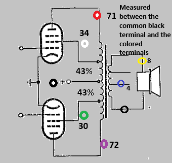
Example of wiring diagram

PCB

Wiring PCB

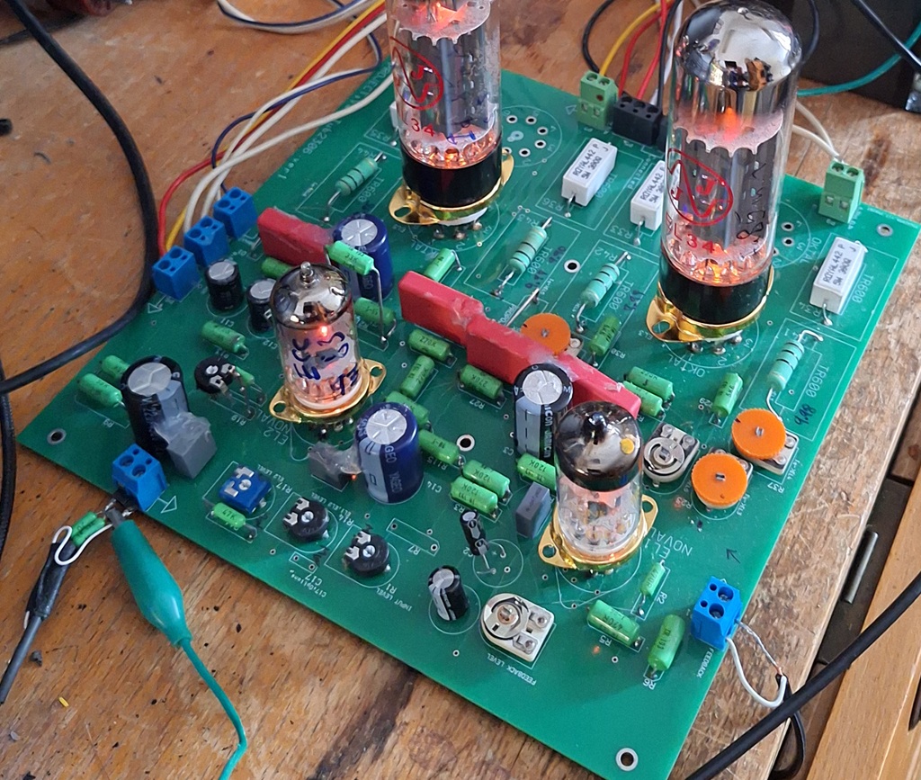
Example of a functional Implemented amplifier
Bill of materials (Some resistors depend on the parameters of the tubes)
changes in the values of the components
| Component | Old value | New value |
| Trimer R16 | 10k | 22k |
| Resistor R18 | 18k | to trimer 10k (position cca 2k7) |
| Resistor R21 | 47k |
Bill of materials
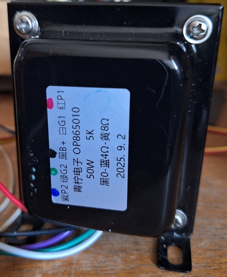
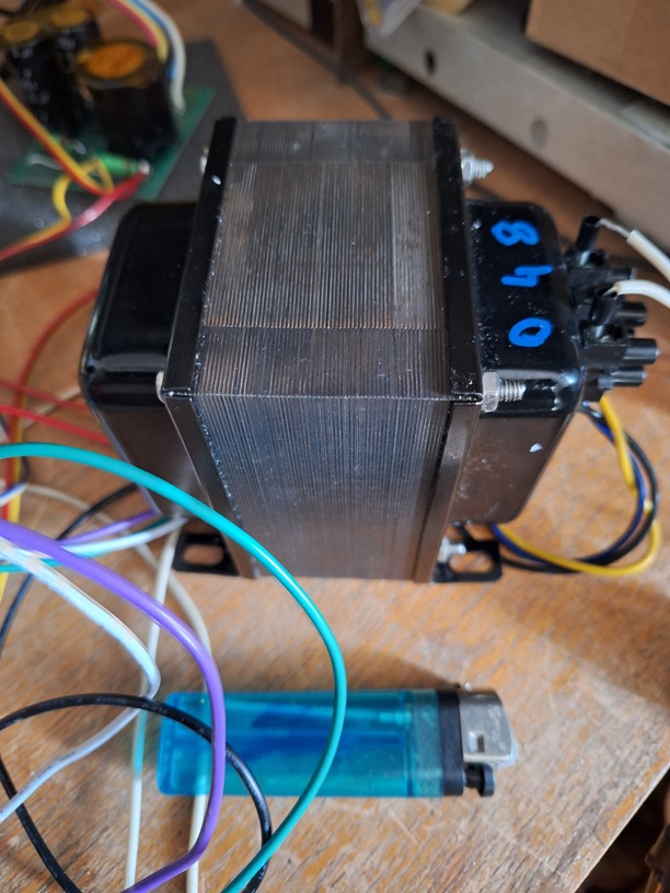
Super linear tap 50W push-pull output transformer
5000 Ohm 50W
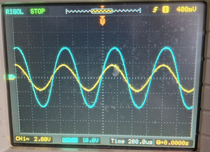
Measured waveforms (JJ Electronic EL34). Project commissioning
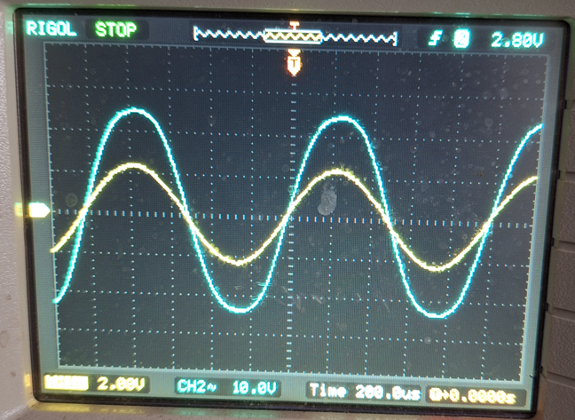
Ia = 80mA, S=cca 7mA| Input signal (Ch2) 2V Output signal 20V (cca 50W/8 Ohm) File 0_1 |
 |
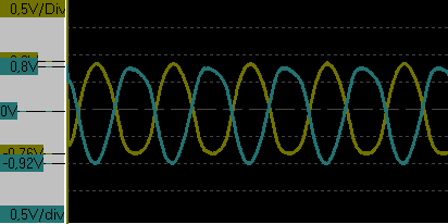
Input signal (Ch2) 0.5V 1kHz Output signal >6V (cca 5W/8 Ohm) The Rezistor R1 in the centre Feedback is not engaged !!! UaEL34 500V. Manufacturer JJ Electronic All other measurements for this level |
 |
|
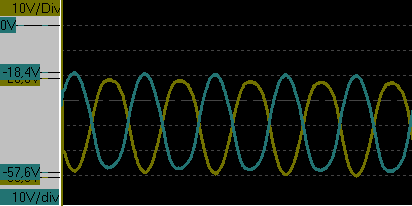
| On the rezistor R41 (Ch1) On the rezistor R43 (Ch2) File 1 |
 |
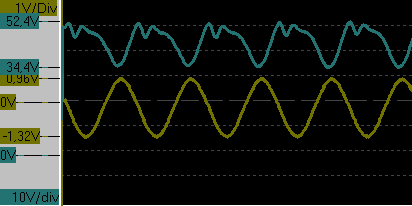
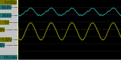
On the grid EL2/2 (Ch1) On the grid EL2/7 (Ch2) File 3 |
 |
|
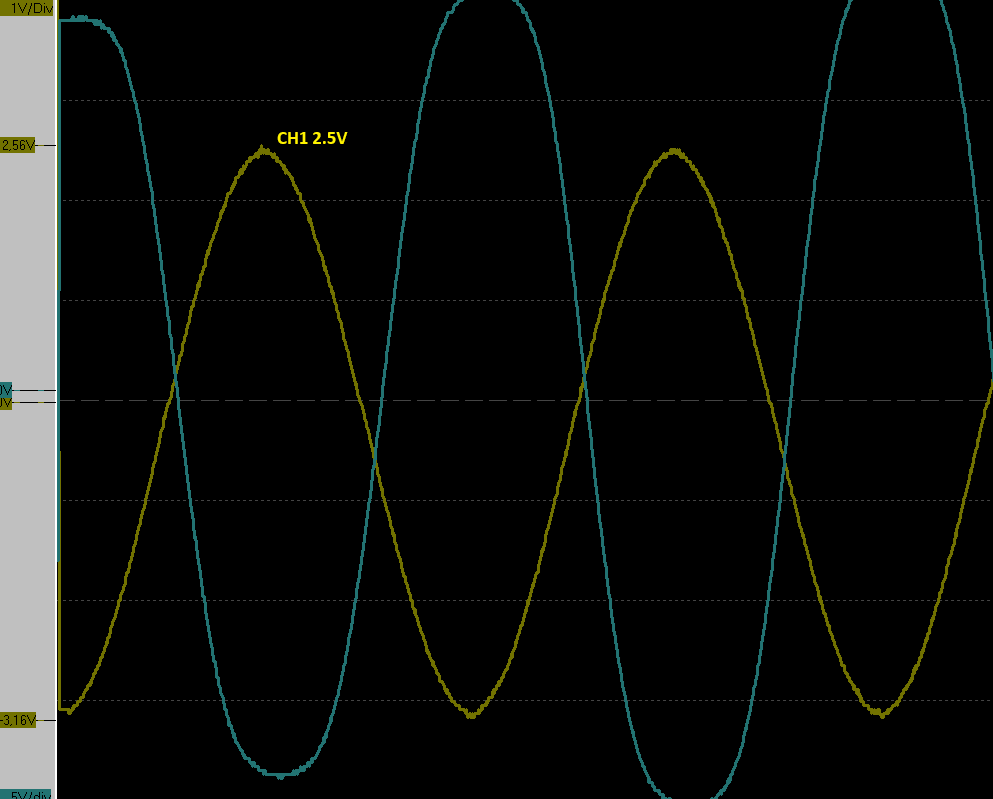
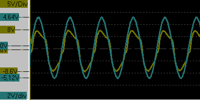
| Input signal (Ch1) 2.5V Output signal 16V (cca 65W/4 Ohm) File 5 |
 |
|||
| Feedback connected Trimer R8 to left 1/4 Input signal (Ch1) 6V Output signal 25V 1kHz from the Out.Transformer File 6 |
 |
Feedback connected Trimer R8 to centre Input signal (Ch1) 4V Output signal 25V 1kHz from the Out.Transformer File 7 |
 |
|
| Feedback connected Trimer R8 to right 1/4 Input signal (Ch1) 2V Output signal 25V 1kHz from the Out.Transformer File 8 |
 |
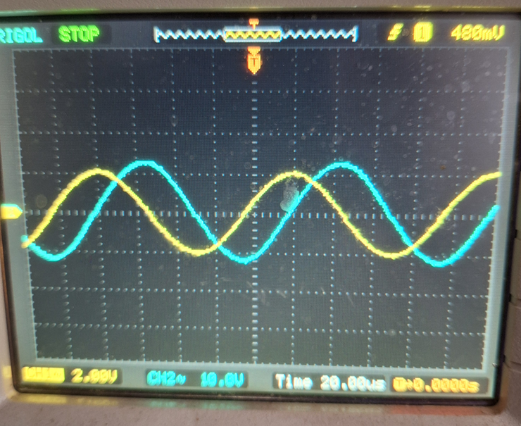
Feedback connected Trimer R8 to centre Input signal (Ch1) 2.4V Output signal 15V 10kHz from the Out.Transformer File 9 |
 |
|
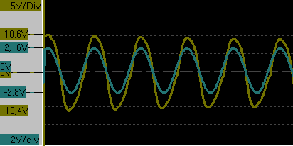
| Used old TESLA EL34 Feedback connected Trimer R8 to right 1/4 Input signal (Ch1) 2.5V Output signal 20V 1kHz from the Out.Transformer File 10 |
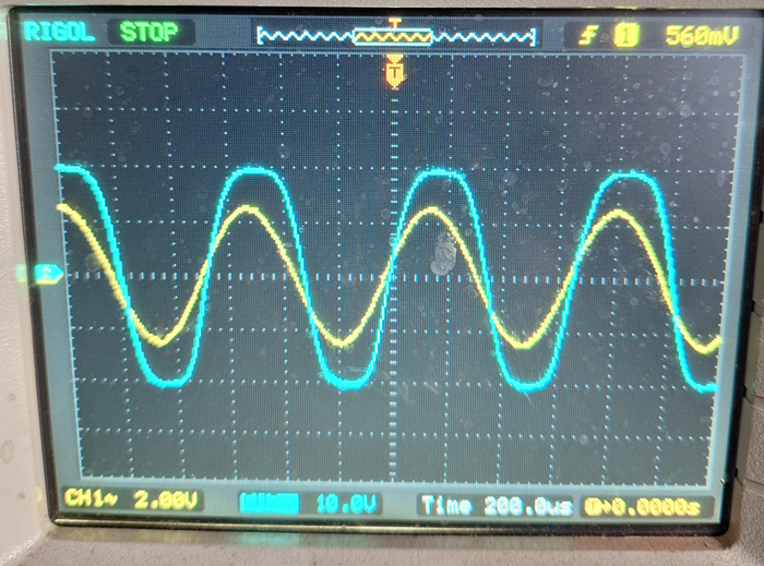 |
Used old RFT EL34 Feedback connected Trimer R8 to right 1/4 Input signal (Ch1) 2.5V Output signal 20V 1kHz from the Out.Transformer File 10 |
 |
|
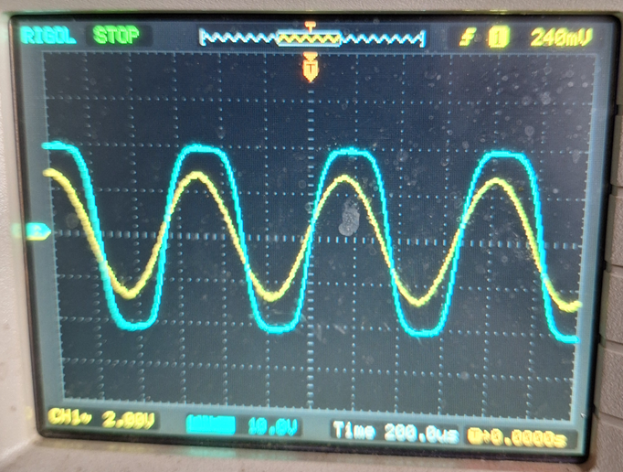
| Used old TESLA EL34, after cathode regeneration! Feedback connected Trimer R8 to right 1/4 Input signal (Ch1) 2V Output signal 20V 1kHz from the Out.Transformer File 12EL |
 |
TESLA EL34, after cathode regeneration! File 12BM |
 |